The latest firmware, version 1_04, has a new "Band Configuration" screen where one may configure the list of supported bands. It is the intention that higher bands will eventually be supported.
I am not so interested in 80 m, so I wanted to see if I already now could get the receiver to work on 17 m and 15 m. With reference to the schematics, I modified the input filter's inductor, L12.
It is tapped at 19, 30, 36, and 41 turns for 20, 30, 40, and 80 m respectively. It resonates with input capacitors C28-C31, with 22, 30, 56, and 220 pF respectively.
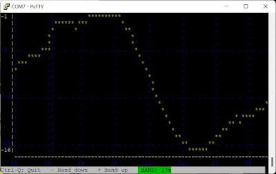
I gave the inductor 36 turns, omitting the extra turns for 80 m, and then tapped L12 after 13 turns. I also also changed C30 to 15 pF. That give me the bandpass characteristics shown below, as analyzed with the built-in analysis function of the QDX:
Here's a new sweep with firmware 1_05_002 (beta) which uses colors which are easier to read:
And now the next thing to do is the transmitter's lowpass filter for 17/15m, which is a bit harder.


Thanks for the info. I am just right before to build my second QDX. QDX Rev.2 is operational, now I have to start with the QDX Rev.3. Due to the absence of any 80m antenna, I am in the same situation. Good luck for further mods and please let us know your success with 17 and 15m. 73s Wolfgang, OE1MWW
ReplyDeleteThese bandpass filters puzzle me as they seem to have multiple peaks. In the plot above you see the response rising to a peak around 30 MHz. I am puzzled as to whether I should use the lowest peak (as i do now) or the second one. Also, the 14 MHz bo filter works well in 18 MHz also
ReplyDeleteguess the first peak should be OK. 73s OE1MWW
ReplyDeleteUsing ELSIE, I designed a LPF for 15M/17M that seems to fit the requirements in simulation. Here are the values: C18=220pF, C12=390pF, C5=220pF, L6=430nH (T37-6:12T) and L2=360nH (T37-6:11T), C9=18pF. I haven't built it yet. As for the BPF, the values I came up with when tacking it onto the LPF are: L12 tapped at 16 turns and C30=62pF, though it has little effect because the shape of the LPF dominates. The LPF reduces second harmonics 30dB, third harmonics are reduced >60dB. When I get time, I'll make the modifications and try it out.
ReplyDeleteVery nice. It's an alternative to the LP filter designed by Ken, g4apb https://groups.io/g/QRPLabs/message/90650
Delete