Showing posts with label ebay. Show all posts

12 April, 2018

Power regulator works as polarity protection

Step-down converter based on LM2596. Note the damaged chip
Ok, now I've done the test. My QRPLabs U3S runs off a 12 Volt power supply. There are two step-down converters, one for 5 Volts for the processor and another adjustable one for the power amplifier, if one can call 0.2-0.5 Watts a power amplifier. See picture of these voltage converters in this post.

I happened to make a new cable for 12 Volts which had the polarities inverted - and puff - there was a noise and absolutely no response from the U3S. I feared that I had blown the entire circuit. As my power amplifier was turned off, only the 5 Volts supply was affected and upon inspection I found that the voltage converter had a destroyed chip.

Since these step-down converter modules are so cheap on EBay, I had a spare. Luckily for me, the U3S worked as it should after the replacement. So the LM2596 can take a reversed polarity and sacrifices itself in order to protect the rest of the electronics. Nice!


This post first appeared on the LA3ZA Radio & Electronics blog.

16 June, 2016

DIY Powerpole voltage and current meters

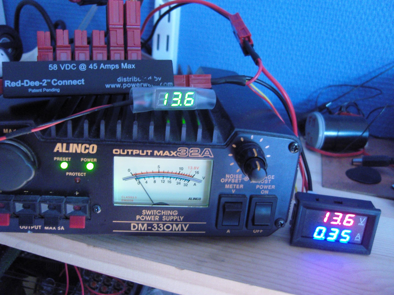
Powerpole voltage and current monitoring is quite nice to have. One can buy commercial meters, but due to the availability of nice and cheap modules, it is very easy to make them oneself.

To the right you'll see my combined voltage and current meter as well as my volt-meter on top of the power supply.

Both of the modules have been bought on Ebay:
  • Miniature 0-30 V DC LED 2 wire Digital voltmeter (371333527599) where the display is 22 by 10 mm. Cost slightly more than $1
  • 0-100 V, 0-10 A Dual Voltmeter Ammeter (262455987311) costing less than $3. The module size is 48 x 29 x 26 mm and the letters are 7 mm tall just like the miniature voltage display.
The wires to the voltmeter are connected directly to Powerpole connectors as shown in the second figure (upper right). Then the voltmeter itself is enclosed in transparent shring-wrap tubing of diameter approximately 20 mm like the one you also can buy on Ebay (252004328030).

The voltage-current meter is a little more complex to connect. First the volt meter has a power lead (4-30 V) and a measurement lead (0-100 V) which are connected together as I will only be using it for 12 Volts. The current measurement loop is between the negative, black, Powerpole connectors. The positive, red, Powerpole connectors are wired together.

I hope this can inspire others to make something similar. And if you do, then please let me know in the comments field!


24 January, 2016

Latest firmware for AP510 APRS tracker is superb

I got my AP510 APRS tracker a little more than a year ago. It kind of worked, but not very well in my car. But after the tracker got a new firmware dated 3 Nov 2015, it has become so much better. Now I can say that it is really useful.

AP510 with original short antenna
and telescopic antenna
Apparently, the Smartbeacon function didn't work properly in earlier versions of the firmware. With some good debugging and error reporting by KC5EVE, Mark, working with the software developer for the AP510, BG6QBV, the annoying errors now seem to be gone. This is all documented in the Yahoo AP510 group.

I have fitted mine with a 16-45 cm telescopic antenna and even when attached to one of the rear headrests in my sedan, the 1 Watt of output power tracks very well.

The map below shows a drive from Telemark, about 100 km west of Oslo, to Oslo with as good coverage as one can expect given the valleys and the availability of APRS digipeaters especially in the western part.


Note the missing tracks east of LA5PPA-1 which are due to a 3.5 km long tunnel,
Strømsåstunnelen, between Drammen and Mjøndalen.

11 December, 2015

Finally got rid of the pirated USB chips for the UV-5R and the AP510

Both the Baofeng UV-5R handheld UHF/VHF radio and the Sainsonic AP510 APRS tracker come with interface cables with pirated chips. These are clones of Prolific USB/serial chips. Since Prolific has taken measures against this, only old drivers will work with them. That means that one has to stop automatic driver updates as explained on the Miklor site for the Baofeng UV-5R. The same is true for the AP510. This is a nuisance.

I got tired of this and got myself some USB/serial modules from Ebay based on the CP2102 chip instead. The cost was US $1.43 a piece so it should be affordable for anyone. I also got some clear heat shrinkable tube.

11 August, 2015

The LM386 Pixie challenge

The Pixie 2 is this minimal transceiver which I and many others have played around with and had lots of fun with. My 80 m version is shown below, but right now it is very popular with some incredibly cheap Chinese ones on sale on Ebay and other places.

The Pixie 2 uses the versatile LM386 amplifier for its audio output. I have shown previously on this blog how its gain can be boosted and how it can implement a CW filter, and also how the muting can be improved. However, during transmission, the LM386 just sits there idle, although it can be used to amplify a sidetone from an external oscillator.

But I'm sure the old 70's LM386 can do better than that. Despite its age, recently some pretty amazing uses of this chip have been demonstrated. It can be used as a regenerative receiver at least up to medium wave frequencies and it can also be used as an envelope detector/demodulator.

The LM386 challenge is this: Is is possible to implement a sidetone oscillator for the Pixie using only the LM386 with as few other components as possible? The output level needs to be controllable in order to make it comparable to that of the Pixie in the receiver mode.

The best data sheet for the LM386 seems to be the one for NJM386 from New Japan Radio Co. It is, as far as I know, the only one which shows the various muting circuits including the one using pin 7 which I have explored. It also shows the LM386 as an oscillator: both a sinusoidal and a square wave one.

In order for the LM386 to be useful as a sidetone oscillator, I believe that the oscillation must take place in the input circuitry. That seems to be the only way to ensure that the output doesn't come out at a blasting full rail-to-rail swing as in the square wave oscillator example in the data sheet.

By the way, the data sheet referred to above is also the basis for the improved Spice model for the LM386 that just was developed. It came partly as a response to my complaint over how poor the present one was. Maybe the new Spice model, developed by EasyEDA, could help solve the LM386 challenge?

07 May, 2015

Ultimate software is up to date

As I have mentioned several times on this blog, I have thoroughly enjoyed WSPR modes ever since Hans, G0UPL came out with the first Ultimate QRSS/WSPR kit.

That means that I have three different versions of the kit. Since Hans has kept on updating the software and even published the compiled versions, it is also possible to upgrade even the old ones.

I have done that and the displays here show the Ultimate 3, the Ultimate 2, and the Ultimate 1 with the latest software.

It is possible to upgrade the chips in-circuit, but I found that it is simpler to remove the chip temporarily from the socket and move it to a simple veroboard with crystal oscillator components. It is connected to my Ebay version of the USBtinyISP.


08 April, 2015

Car upgrade to LEDs

It was time to upgrade the interior lights in my 2004 Volvo. I got some lamps from Ebay specified as 42 mm LED Festoon, 80-85 lm, 12V. As many others have experienced also, they kept on glowing faintly after the door was closed. But when the ignition was turned off the lamps were completely off also, so there was no danger of draining the battery. Still this is not the way one expects lamps to behave.

One can get more expensive LED lamps which avoid this faint glow, "Canbus error free" seems to be the way to specify this. But mine were of the plain type, and the problem seems to be the leakage current in the FET switches that turn the lights on and off. It is tiny, but enough to give a voltage large enough to turn the LEDs on. An additional resistor load will lower the voltage below that threshold.

09 February, 2015

Finally got my Ultrafire WF-501B as I wanted it

As I wrote in my blog post a few days ago, I got the intensity down for night vision for my red flashlight. But I wasn't quite happy with the level and wanted to reduce it even more. To do that I had to unsolder 6 of the 8 AMC7135 350 mA constant current ICs on the PCB of the AMC7135*8 2800mA 4-Group 5-Mode Circuit Board.

These constant current chips are all run in parallel with the VDD input for control. The 8-pin Atmel ATtiny13A chip controls all VDD inputs in parallel from its pin 6. When the VDD pin is low there will be no light. I haven't measured this, but I am assuming that this pin is pulsed in order to reduce current down from the maximum.

My measurements for the High, Medium, and Low settings are:

04 February, 2015

Dimming my Ultrafire WF-501B

I got this red LED flashlight as a Christmas present. But unfortunately the intensity was way too high for what I intended to use it for. A soft red light preserves your night vision, and is ideal for use with a telescope in the dark as was my intention. But if the intensity was as high as before the modification, night vision would suffer anyway.

I then found this YouTube video describing how the controller circuit board could be replaced by one with more functions. As recommended I therefore ordered an AMC7135*8 2800mA 4-Group 5-Mode Circuit Board with 8 AMC7135 current regulators in parallel. The image shows the original circuit board as connected before the modification in the front in the image and the new one behind it.

The new board gave me the choice of one of 4-groups:
  1. 3-mode: Lo (5%) - Hi (100%) - Strobe
  2. 3-mode: Lo (5%) - Mid (30%) - Hi (100%)
  3. 2-mode: Lo (10%) - Hi (100%)
  4. 5-mode: Lo (5%) - Mid (30%) - Hi (100%) - Strobe - SOS

15 August, 2014

New gadget measures negative resistance

If you are like me, you appreciate electronic gadgets with dials and displays. So when I discovered this "USB detector",  I thought to myself that I really always wanted to know the voltage as well as the current consumption of my USB devices. And since it is more or less impossible to connect a multimeter, this is exactly what I need.

The device fully satisfied my curiosity. Actually one surprising result was that the charger for my Samsung Galaxy Note 8 has a negative output resistance.

30 May, 2014

Temperature compensation for an Arduino ultrasonic distance sensor

161.3 cm
27.0°  347.7 m/s
Ultrasonic distance sensors can find the range out to 2-4 meters and are popular in e.g. robotics. Here I look at how the accuracy can be improved by compensating for the variation of speed of sound with temperature. It actually varies quite a lot in air and around 0 C it is:

      c = 331.3 + 0.606 * T

where c is in m/s and T is in C. The formula is good to up to at least +/-30 C. There is also a dependence of humidity, but as it is so small it is neglected here.

The equation can be analyzed for sensitivity (a little bit of differentation, you know). The result is that a two-way range measurement creates an error of 1.8 mm/C/m. That means that with a 4 degree C error, the deviation will be 14.4 mm at a range of 2 meters. Not a lot, but more than the wavelength which is 9 mm at 40 kHz. Considering how easy it is to compensate for, then why not give it a try?

25 February, 2014

Show off your project in a clear top tin

We all want to package our electronics projects in some nice enclosure. An Altoids tin is often used - and I have used that a lot myself. But for slightly larger projects, the tin shown below is a better alternative. In addition it has a clear top, so displays can be viewed and the nice layout of your electronics can be admired. 


05 January, 2014

Car keys in the 70 cm band

The 70 cm amateur band covers from 432 to 438 MHz in Norway and radio amateurs have primary status. Secondary users are among others remote controls for keyless entry systems for cars since it is an ISM (Industrial, Scientific, Medical) band also.

I wanted to see how much traffic the secondary users generate. I used my RTL-SDR dongle with RTL2832U and R820T chips that I bought on Ebay for less than 10 US$ almost a year ago. The antenna was a roof mounted HL-B61N vertical (1.7 m long). This is the output of the SDR# program:

Press image for a larger view

It is clear that this band is pretty busy! No wonder that amateur repeaters have had to move their input frequency away from this frequency range. 

The waterfall covers 10-12 seconds and there are up to 10 transmissions simultaneously. The nominal frequency is 433.92 MHz and there are emissions from 433.75 - 434.05 MHz. I live in a suburban area with about 1 million people, but I imagine that I only pick up a small part of the remotes in this area since the car key transmitters are very weak. Anyway it demonstrates both the versatility of the cheap software defined receiver dongle, as well as how busy the band is. 

Related posts:

13 August, 2011

Small voltmeter for a QRP rig

AT Sprint rig in an Altoids box, itself contained in a video case.
Digital voltmeter in lower left corner shows 12.0 Volts.
(Click for larger image)
Every battery-operated rig needs a voltmeter. I had a small analog voltmeter for my AT Sprint QRP (= low power), 4 Watt rig, but after it failed I wanted to upgrade it to a digital one. I found a miniature meter on Ebay which is perfect for a QRP rig and which I recommend.