Showing posts with label QRPLabs. Show all posts

27 March, 2025

QMX+ mechanical improvements

My QMX+ has some minor mechanical improvements:
  1. Slimmer knobs. I decided to replace the knobs as I often touched the bottom one while adjusting the top one and vice versa. The slimmer knobs solved that. I found knobs on AliExpress with the same looks, only a smaller diameter as the image shows. Unfortunately they don't have screws, so they aren't so well attached as the original ones.
  2. Folding laptop feet which I first saw on the AE5X blog.

24 January, 2025

A QMX+ coming together

I got an unassembled QMX+ for Christmas this year, and here are pictures of it coming together. First the winding of toroids for the low-pass filters:

12 October, 2024

The Little Known Fourth Method of Generation of Single-Sideband Signals

Envelope Elimination and Restoration, from Kahn 1952 
There is a method for SSB generation which is now becoming popular with digital signal generation and digital output stages. This is the Envelope Elimination and Restoration method or Polar Modulation method. The signal is interpreted as a complex signal in the polar format, i.e., with an envelope and a phase.

This method is receiving renewed interest among radio amateurs as it is used in the SSB implemention of e.g. the interesting QRPLabs QMX transceiver. 

In the QMX a single frequency signal (the phase) is generated in the digital domain and then phase modulated (upper branch of figure). It then has a digital output stage with very high efficiency as it only switches between on and off. The output stage is amplitude modulated with the envelope signal from the lower branch.This gives a much more efficient power amplification than is possible with the three conventional methods.

The three methods

How does it compare with other methods? In 1956, Donald K. Weaver, Jr. wrote a paper with title "A Third Method of Generation and Detection of Single-Sideband Signals".

28 April, 2023

3 tips for not blowing the finals of the QDX transceiver

I have now used both the low- and the high-band QDXes daily as EA8/LA3ZA for a period of two weeks without destroying the four BS170 final transistors. Here are some procedures and tips.

But first, I do actually have experience in blowing the finals. That happended under testing prior to leaving, and all it took was 9.5 Volts for my 9 V build and what I thought was a dummy load, but which might have been an open circuit load. One BS170 developed a short between drain and gate with the result that 9.5 Volts was passed directly into the outputs of the driver IC5, 74ACT08, so IC5 blew as well.

My three tips for avoiding such failures are:

18 February, 2023

QDX Twins 80-10 m

My QDX twins from QRPLabs: 

  1. On top, the high-band version, 20-10 m, with a revision 4 PCB
  2. In the bottom, the original 80-20 m version with a revision 3a PCB
Both have been assembled for 9 Volts operation nominally.

My wife and I have identical twins in real life and at times one of the ways to distinguish between them was by different colors. Here it is the same, so the high-band QDX has a yellow LED and the low-band one has a green LED.

10 July, 2021

Coordinated WSPR band hopping with the QRPLabs U3S

There is a recommended sequence for multi-band transmission on WSPR. It is given in the K1JT WSPR documentation. If enough receivers follow this sequence, then presumably letting WSPR transmissions also follow it, will increase the chance of detection. 

The recommended band hopping sequence cycles through 10 bands over a 20 minute period according to this table:

Band (m)   160  80  60  40  30  20  17  15  12  10
UTC Minute  00  02  04  06  08  10  12  14  16  18
            20  22  24  26  28  30  32  34  36  38
            40  42  44  46  48  50  52  54  56  58

The multi-band U3S is capable of adhering to such a sequence. There are however three considerations that need to be taken into account. 

03 March, 2021

QRPLabs 25 MHz TCXO performing well in the U3S

I have tried several oscillators in the U3S QRSS/WSPR transmitter from QRPLabs. First an analog devices DDS, then a Silicon Labs oscillator chip running from an ordinary 27 MHz crystal, and then QRPLabs own oven controlled oscillator. I thought I had managed to control the drift when I got the oven controlled oscillator. But then after a while it started drifting again. I didn't want to go through its rather cumbersome calibration procedure once more so I gave it up recently when the TCXO module became available. This tiny module is shown in the first image.

24 April, 2019

The Ultimate WSPR Spot - part 2

Being spotted by the designer of my WSPR transmitter must be the ultimate WSPR spot! Perhaps only surpassed by being spotted by the designer of the mode himself, K1JT, Joe as I was four years ago.

It is Hans, G0UPL, of QRPLabs who is the designer of both my U3 to the left (turned off) and the U3S to the right. The latter was the active transmitter at the time of the spot below.


By the way, this is a line from VK2TPM, Peter's excellent WSPR Watch app for Ipod.


23 February, 2017

Comparing two antennas with WSPR

Ultimate 3S with 5-band relay module in front,
variable LM2596 power supply (with voltmeter) for
the power amplifier behind left,
a variable LM2596 supply set for 5 Volts for the Ultimate 3S
in the middle, and the antenna switch to the right in the back.
WSPR - The system for Weak Signal Propagation Reporter makes it easy to compare antennas if your transmitter can instantly switch antennas. The system shown here can send on antenna 1 for almost two minutes and then switch immediately to antenna 2 for the next transmission.

The Ultimate 3S already has software that supports that and application note 3 from QRPLabs (Controlling additional relays using the Ultimate3S “Aux”) describes how. I built mine following that note and the experience from EA1CDV.

The circuit is controlled from pin D7 and consists of a transistor, a relay, a resistor and an electrolytic capacitor. In addition I have two LEDs that indicate which antenna which is in use. In the first picture the green LED in the back right under the BNC antenna connector shows that antenna 1 is connected.

07 August, 2014

WSPR on 5 bands

For the first time ever I have been spotted on all the five bands that my Ultimate3 QRSS/WSPR kit (G0UPL design) is transmitting on. This is after 2-3 days of transmitting.


Right now I am using the beacon for discovering if the bands should open up on 24 and 28 MHz. The other three bands, and especially the 14 MHz band, serve as references to tell me that the transmitter is working. My antenna is not so optimal so I would be surprised if I am spotted far outside Europe. It is an end-fed 5 m long half wave vertical dipole which isn't too bad for 28 and 25 MHz, and probably not very good at all on 21, 18, and 14 MHz.

24 April, 2014

Pulled out my dummy load tonight

Press image for a better view of the dummy load
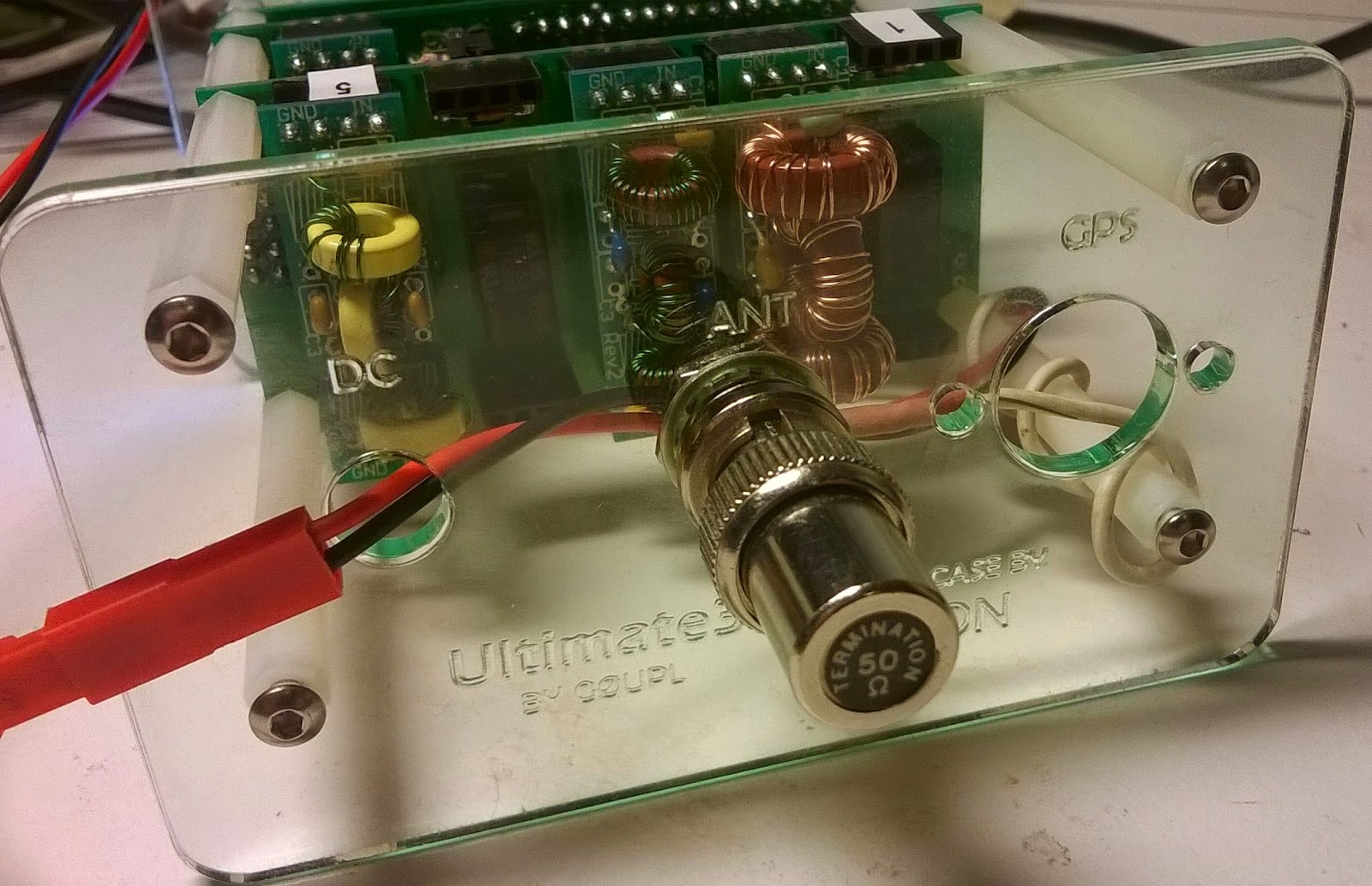
Testing a transmitter means the use of a dummy load. Trying to be considerate, I don't want to cause unnecessary interference with my signals. So when I want to test my Ultimate 3 QRSS/WSPR kit I also pull out one of my dummy loads.

It measures just 9-10 mm across and is the size of a BNC connector. It is simply one of the many Ethernet terminations that I have lying around. Its built-in 50 ohm resistor is rated at something like 0.25 W. Considering that the kit outputs something like 200 mW that should mean that there is enough margin and no forced air cooling or liquid cooling is required.