Showing posts with label homebrew. Show all posts

08 October, 2019

6 m Antenna Inspiration

It's nice to see that my antenna article in Amatørradio no. 3 this year has inspired others. In no. 4, LA1AEA, Alfred, has written about how he made his own. It helped him try the 6 meter band this summer. Given his location in the very far North of Norway (Finnmark), I'm impressed by contacts that he had all the way to Greece, 3500 km away.

He writes: "LA3ZA Sverre Holm wrote an interesting article in no 3, 2019 with title "A Moxon summer antenna for 6 meter." I was inspired to try myself with some simple materials that I had available. For a long time I have considered the 6 m band to be unusable from here way up North. But this shows how wrong one can be."


This blog post first appeared on the LA3ZA blog.

13 May, 2019

More spurs than I had hoped for

My Just good enough 10 MHz reference based on the direct output of a Neo-7 GPS module, described in detail before on this blog, is good in keeping long-term frequency stability. Short-term stability and phase noise is as expected not so good. When connected to the reference input of my Elecraft K3 and listening to an outdoor antenna, I get quite a substantial amount of spurs around 10 MHz radiating from the GPS module. But since the K3 itself does averaging over a second or so, this is fine from the point of view of keeping accurate frequency.

12 April, 2018

Power regulator works as polarity protection

Step-down converter based on LM2596. Note the damaged chip
Ok, now I've done the test. My QRPLabs U3S runs off a 12 Volt power supply. There are two step-down converters, one for 5 Volts for the processor and another adjustable one for the power amplifier, if one can call 0.2-0.5 Watts a power amplifier. See picture of these voltage converters in this post.

I happened to make a new cable for 12 Volts which had the polarities inverted - and puff - there was a noise and absolutely no response from the U3S. I feared that I had blown the entire circuit. As my power amplifier was turned off, only the 5 Volts supply was affected and upon inspection I found that the voltage converter had a destroyed chip.

Since these step-down converter modules are so cheap on EBay, I had a spare. Luckily for me, the U3S worked as it should after the replacement. So the LM2596 can take a reversed polarity and sacrifices itself in order to protect the rest of the electronics. Nice!


This post first appeared on the LA3ZA Radio & Electronics blog.

16 June, 2016

DIY Powerpole voltage and current meters

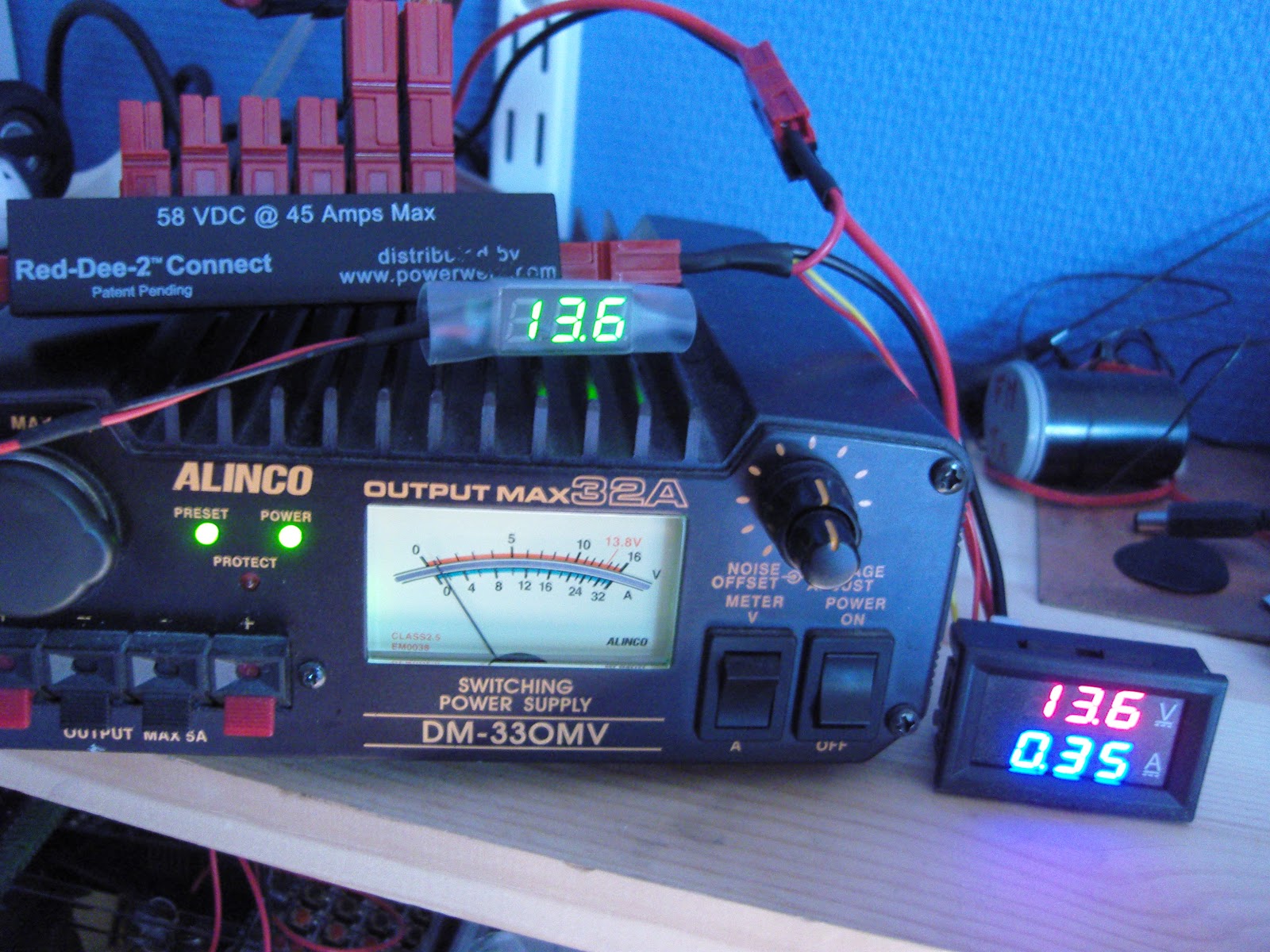
Powerpole voltage and current monitoring is quite nice to have. One can buy commercial meters, but due to the availability of nice and cheap modules, it is very easy to make them oneself.

To the right you'll see my combined voltage and current meter as well as my volt-meter on top of the power supply.

Both of the modules have been bought on Ebay:
  • Miniature 0-30 V DC LED 2 wire Digital voltmeter (371333527599) where the display is 22 by 10 mm. Cost slightly more than $1
  • 0-100 V, 0-10 A Dual Voltmeter Ammeter (262455987311) costing less than $3. The module size is 48 x 29 x 26 mm and the letters are 7 mm tall just like the miniature voltage display.
The wires to the voltmeter are connected directly to Powerpole connectors as shown in the second figure (upper right). Then the voltmeter itself is enclosed in transparent shring-wrap tubing of diameter approximately 20 mm like the one you also can buy on Ebay (252004328030).

The voltage-current meter is a little more complex to connect. First the volt meter has a power lead (4-30 V) and a measurement lead (0-100 V) which are connected together as I will only be using it for 12 Volts. The current measurement loop is between the negative, black, Powerpole connectors. The positive, red, Powerpole connectors are wired together.

I hope this can inspire others to make something similar. And if you do, then please let me know in the comments field!


11 April, 2016

Improved GPS reception with a ground plane

My poor-man's 10 MHz reference based on the Ublox Neo-7M GPS module didn't always receive GPS satellites. Since I rely on reception indoors, conditions were sometimes too marginal to lock the oscillator output to 10 MHz. Inspired by the QRPlabs GPS module of Hans Summers (G0UPL) with its large 6 x 6 cm PCB groundplane, I therefore decided to do something similar.

The first picture shows the unit with the 8.5 x 6.5 cm single-sided PCB ground plane attached with double-sided tape. It definitely helped make indoors reception in my shack much more reliable. In addition to the improved conditions for the patch antenna, it probably helps too that the antenna now is shielded from the digital circuitry of the GPS module, the 10 MHz pulse shaper, and the USB interface. I also added a small LED to the right so that I could see from the outside whether the GPS locks properly.

The second picture shows the interior prior to adding the ground plane.

This post is a continuation of these other posts about the 10 MHz reference:
  1. Just good enough 10 MHz reference (3 Oct 2015)
  2. Better with SMA (15 Oct 2015)
  3. Curing amnesia in the 10 MHz GPS reference (19 Nov 2015)


15 October, 2015

Better with SMA

I had some trouble closing the lid on the "Just good enough 10 MHz GPS reference" due to the size of the BNC jack. Therefore I changed it to an SMA (SubMiniature version A) female jack. A thin cable connects it to the K3's SMA input and there is no need for any SMA-BNC adapter on that end.

At the same time I moved the GPS antenna to a more central location in the tin, in the hope that the walls of the tin would interfere less with GPS reception. That's the theory anyway, if it matters much in practice is a different story.

Actually, I think I'm going to use SMA more often with these clear top tins and also Altoids tins. They take up much less space and are easier to install and to work with.

There aren't any high power applications for circuitry in such tins, so I cannot so any reason why the SMA won't work just as well or even better than the BNC.


Other related posts about the 10 MHz reference:

03 October, 2015

Just good enough 10 MHz GPS reference

Some time ago I noticed that the Ublox Neo-7M GPS has a 10 MHz output which is locked to the GPS system's accuracy. Most people kept saying how useless it was due to excessive jitter unless it was cleaned up with a phase locked loop of some sort.

At about the same time I installed the external reference input for my Elecraft K3. The K3EXREF enables the K3's frequency to be locked to an external 10 MHz reference. What struck me was how its function is described:


This got me wondering if the Neo-7M would be just good enough as a reference and that all the averaging internally to the K3 would take care of the jitter.

29 April, 2015

First 475 kHz WSPR decoding

Tonight I made the first successful decoding of WSPR on the 630 m band. What inspired me was all the talk on the Elecraft reflector on the new synthesizer which in addition to having less phase noise, also allows the K3 to go below 500 kHz. I don't have that synthesizer, but the discussion reminded me of the low frequency converter I built many years ago. It converts 0-1 MHz to 14-15 MHz. Using the KXV3 transverter interface of the K3 it was easy to interface and get up and running.

The first signals I decoded are shown in the water fall above, and their origin in Germany and the Netherlands is shown in the next figure.

According to WSPRnet, PA0A's 2 Watt transmitter is 784 km away from me, and DK7FC's 1 Watt is 1164 km away.

The converter is quite simple and is based on a 74HC4053 switch used as a mixer with a 74HC04 for a 14 MHz oscillator. It is the design of SM6LKM, but with a different oscillator frequency and a simplified output filter compared to his. It is one of many small projects that I have built in Altoids tins.

The antenna used was my trusty old 80 meter horizontal loop which has been the main work horse for making my 8-band DXCC (more than 100 countries on all bands 3.5 - 28 MHz) possible. It is fed with ladderline into a 4:1 Elecraft balun in the shack.

Perhaps the next step is to finish the 475 kHz filter of my Ultimate 3 WSPR transmitter and see if others can receive me? That is going to be more of a challenge antenna-wise.


31 March, 2015

Low power longwave transmitter experiment

Many places in the world, low power transmitters in the medium wave band are allowed. I am talking about regulations like in the US where FCC part 15 allows up to 100 mW input.

In Norway we have a particular permission for members of the Norwegian Radio Historic Society to transmit up to 500 mW on 216 kHz in the longwave band. I'm not sure if this is output or input power [it's output power]. The permission is meant to cover a personal collection of historic radios. The frequency is the one used by the main transmitter north of Oslo from 1954-1995 running 200 kW. The frequency is still allocated to Norway, so I guess that is why we may use it this way.

05 September, 2014

So you want to play with a Pixie 2?

My own surface mount version of the Pixie2
Here's a guide in table format to minimalistic single-band amateur radio transceivers. The Pixie 2 and related kits are fun to build, yet they perform well enough to be used, although with some effort, for real contacts.

The idea of using the power amplifier transistor as a mixer seems to come from George Burt - GM3OXX - whose five transistor FOXX was described in 1983 in SPRAT. The basic design of the oscillator, PA/mixer and the simple keying has been more or less unchanged since Oleg Borodin - RV3GM - described the four transistor Micro-80 in 1992 in SPRAT. Then Dave Joseph - WA6BOY - replaced two of those transistors with the LM386 audio amplifier in the Pixie 2 (QRPp 1995). Most later versions are variants of these designs.

Here's the table of Foxx, Micro 80, and Pixie 2 kits:

03 May, 2014

Practical Wireless with the LM386 unleashed

"Improving the LM386 Audio Amplifier" is the title of always inspiring Rev. George Dobbs G3RJV's column in this month's Practical Wireless. George talks about the basic amplifier with a voltage gain of 20 (26 dB) and how it is straight forward to increase gain to any value up to 200 (46 dB). The article then shows how it can be built dead-bug style.

Then he goes on to talk about various ways to improve the circuit such as for hiss reduction and even higher gain. In that connection he also mentions my article "Unleashing the LM386" from SPRAT in the Autumn of 2003. That circuit was an enhanced version of the high-gain circuit of Kazuhiro Sunamura JF1OZL. Basically it increases the gain to up to more than 70 dB, enough for it to drive a loudspeaker. My circuit also adds bandpass filtering. All this is achieved by adding only 5 passive components to the basic amplifier. The circuit was recently revisited in SPRAT by Johnny Appel SM7UCZ. He added a 40 dB Darlington pair preamplifier for even further gain.

The bandpass filtering (not low pass as the article says) is due to the series resonance of 100 uF and 1 mH which happens at about 500 Hz making it a nice CW filter.

25 February, 2014

Show off your project in a clear top tin

We all want to package our electronics projects in some nice enclosure. An Altoids tin is often used - and I have used that a lot myself. But for slightly larger projects, the tin shown below is a better alternative. In addition it has a clear top, so displays can be viewed and the nice layout of your electronics can be admired. 


13 October, 2013

The simplest possible AM transmitter

Here's a design for a 1 MHz amplitude modulated (AM) transmitter. I've been looking a while for something like this, a simple short range AM transmitter for the medium wave band, as I needed something for demonstration of my collection of old radios.

The result is the AM transmitter shown here in an Altoids tin on top of a Radionette Kurér radio. This is a portable tube radio from the 1950's. Several hundred thousands were produced, and it was exported from Norway to 60 countries. It is still popular among collectors.

The transmitter is as simple as it gets. The heart of it is a 1 MHz crystal oscillator in a can. Its 5 Volt power is modulated via an audio transformer, one taken from the output of a transistor amplifier (primary 147 ohms - secondary 3 ohms). I drive the modulator from my cell phone into the low resistance side of the transformer and get good audio when the phone's volume is set to maximum.

02 June, 2013

The advantage of the single-lever paddle

My single-lever PCB keyer.
It may seem like a bad idea to downgrade from a dual-lever paddle and iambic keyer to a single-lever paddle. It must be inefficient since each individual dash and dot has to be generated by a right or left movement of the paddle. Despite this, many of the champions in the High Speed Telegraphy competitions use single-lever paddles, often home-made ones. How can that be?

K7QO, Chuck Adams, wrote "Using an Iambic Paddle" and compared the dual-lever paddle with the single-lever with respect to number of movements. If all 26 letters of the English alphabet and the numbers from 0 to 9 are sent, the single-lever paddle requires 73 strokes while a dual-lever and an iambic keyer requires 65. This is 11% less.

But when N1FN, Marshall G. Emm, wrote "Iambic Keying - Debunking the Myth" he analyzed the 7 letters that are faster to send with an iambic keyer - C, F, K, L, Y, Q, and R - and found that only one of them, the L, is among the 12 most frequent ones in English reducing the gain in efficiency to only 5%. He illustrated it this way:

Guess what't wrong with this figure? He didn't see the R and forgot that it is also among the most frequent letters.

19 February, 2013

1 Volt/2 Volt Transceivers

Transceivers with a power supply of 1 and 2 Volts, how much can one achieve with that? Well, actually quite a lot according to DL2AVH, Helmut, who together with DL4ALJ, Gero, wrote two articles about that in the German QRP-Report in 2011. I am impressed by the output power, up to 200 mW with one battery cell (1.5 Volts) and 0.5 Watts with two cells.

I wrote about this in April last year where I also mentioned that the 1 Volt design from 2000 later had been corrected. Those corrections can be found in the article in QRP-Report 3/2011: "Niederspannungs-Schaltungstechnik - der 1-V- und der 2-V-transceiver" (Low voltage circuit technology - the 1 Volt and the 2 Volt transceivers). The improvements are concerned with better input filtering at 14 MHz with a quartz crystal in the front-end filter and better efficiency in the mixer and removal of an audio stage in the direct conversion receiver. This design only uses bipolar transistors and no ICs.

08 January, 2013

GSM phone power control and signalling

When you measure the energy out of a GSM cell phone at the moment of initiating a call, you get the picture to the right. It shows the first 15 seconds.

For the first 3.5 seconds there is the signalling between the phone and the base station. Then the connection is established, but after some time (at 4.2, 5.6, 7.5 and 9.5 seconds) one can see how the phone turns the power down, according to the commands it gets from the base station.

23 October, 2012

A Useless Machine with delay and howl

The useless machine or ultimate machine originates from Claude Shannon, the scientist who figured out how to find the channel capacity in a communications system. I bought the basic machine as a kit from Solarbotics.

But then I added a few features:
  • A delay circuit that makes it look more alive as it gives the impression of doing some thinking before it responds to the switch.
  • Sound that varies with how open the lid is and the amount of light that hits the photosensitive resistor. It was inspired by the design of the Growl and Scream Altoids of FightCube.
  • A couple of LEDs, a red one when it opens and a blue one when it closes.
The circuits were built on small pieces of veroboard and the circuit diagram can be downloaded from here. In retrospect I'm not completely happy with the sound, it could have growled and screamed even more, but then how much effort can one really justify putting into a project which is - useless - anyway?

20 September, 2012

My first 24 hours on WSPR

My first beacon on 30 m, a free-running Ultimate QRSS kit (no GPS) has now been running for a full 24 hours using the Weak Signal Propagation Reporter (WSPR) mode. The figure comes from the WSPRnet page.

With an output power of about 150 mW to an 80 m horizontal loop it has not been possible to reach beyond Europe so far. Perhaps this will happen in the future with better conditions and/or with some more output power.

Added 26.9.2012: I made it for the first time across the Atlantic!
Timestamp           Call       MHz         SNR Drift  Grid      Pwr Reporter   RGrid      km      az
2012-09-26 00:50, LA3ZA, 10.140262, -26,   -2,   JO59fu, 0.2, WB2EEE, FN21xh, 5852, 290

16 September, 2012

Altoids Projects

Press image for magnification
I like to build small electronics projects and like many others I have found the small Altoids tins to be excellent enclosures. 

These tins are inexpensive, well shielded, easy to work with, and least but not least they enable you to make experimental circuits that are sturdy enough that they can be reused later.

Pictured here is a collection of projects I have built over the years with the hope that  they may inspire others.

16 August, 2012

Transformerless tube power supply

In 2012 bulky power transformers that work directly from the power grid at 50/60 Hz have mostly disappeared. My objective here is to modernize the power supply for a one-tube transmitter in the same way.

The circuit is based on an electronic transformer for LED or halogen lamps. Electronic transformers usually have a minimum power rating, below which they will not start. This one can tolerate a lower load than most and gives out 12 Volts for a load from less than 10 W and up to 60 W.