23 February, 2017
Comparing two antennas with WSPR
The Ultimate 3S already has software that supports that and application note 3 from QRPLabs (Controlling additional relays using the Ultimate3S “Aux”) describes how. I built mine following that note and the experience from EA1CDV.
The circuit is controlled from pin D7 and consists of a transistor, a relay, a resistor and an electrolytic capacitor. In addition I have two LEDs that indicate which antenna which is in use. In the first picture the green LED in the back right under the BNC antenna connector shows that antenna 1 is connected.
27 November, 2016
Even better low-pass filters for transmitters
The last issues of QEX have featured two interesting articles by Gary Cobb, G3TMG. He outlines the advantage of using Zolotarev designs for the harmonic suppression filters of transmitters, giving even better suppression of the second harmonic than the more common Chebyshev or quasi-elliptic filters.
My interest in this was triggered by the test of the Ultimate 3 QRSS/WSPR kit from QRP Labs in the Nov 2016 QST. The review was positive overall, but it was remarked that the harmonic suppression does not meet FCC requirements (-43 dBc or better). I am not sure whether this is due to PCB layout issues, or if better filters can alleviate it, but I note that the design uses the simplest filter of the ones I have listed here.
The evolution of filters for use for harmonic suppression follows at least these three steps:
![]() |
| Chebyshev low-pass filter from the GQRP data sheet (issue 1) |
The evolution of filters for use for harmonic suppression follows at least these three steps:
06 November, 2016
Yet another Arduino clock
Does the world need more Arduino clocks? Maybe not.
But I needed another Arduino project as I had made a K3NG morse keyer. I love this keyer because it is unique in supporting a display where you can see what you send. But I wasn't using the morse keyer all the time, so I wanted the hardware to serve two purposes. That's the excuse for also making a clock.
Its main features are:
But I needed another Arduino project as I had made a K3NG morse keyer. I love this keyer because it is unique in supporting a display where you can see what you send. But I wasn't using the morse keyer all the time, so I wanted the hardware to serve two purposes. That's the excuse for also making a clock.
Its main features are:
- Controlled by a GPS module outputting data over a serial interface, and handled with the TinyGPS++ library
- Shows raw GPS data such as UTC time and date, position, altitude, and number of satellites
- Shows derived GPS data such as 6-digit locator
- Finds local time and handles daylight saving automatically using the Timezone library
- Finds local sunset and sunrise, either actual value, or civil, nautical, or astronomical. The library is Sunrise.
- The clock also gives local solar height based on the Sunpos library from the K3NG rotator controller.
- Finally, the clock also provides the lunar phase based on ideas found here.
The hardware for the K3NG keyer includes a speed pot and a memory bank selector (to the right) as well as four push buttons on top for selecting memories. The pot now controls the intensity of the display, but the bank selector switch is not used. Of the four push buttons, only button 1 is used (later two are used). With it one can toggle the clock through various displays as shown below.
22 October, 2016
What it takes to make the AP510 APRS tracker useful
This small VHF APRS tracker can easily be improved with some simple measures:
The post "What it takes to make the AP510 APRS tracker useful" first appeared on the LA3ZA Radio & Electronics Blog.
- The 1 Watt of output power is often too little to reach the desired APRS digipeater reliably enough. It is much simpler to improve the antenna than to add an amplifier and it can be done as follows:
- Use a longer telescopic antenna. In the picture I have used an antenna that can be extended from 16.5 cm to 45.2 cm. Depending on how you use the tracker, always extend the antenna as much as practically possible.
- Add an external counterpoise or "tiger tail" of length a quarter of a wavelength. That's about half a meter. In the picture it is fastened on the antenna's BNC connector by means of an 8 mm ring terminal.
- Update the firmware, if you haven't done so already, to the version from 3 Nov 2015. I have written before about my experience with that firmware.
- Get rid of the pirated USB chip in the interface cable. I did that last year and now interfacing it to the PC and updating it is so much simpler.
The post "What it takes to make the AP510 APRS tracker useful" first appeared on the LA3ZA Radio & Electronics Blog.
16 June, 2016
DIY Powerpole voltage and current meters
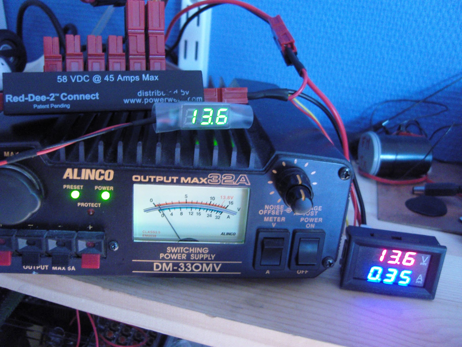
Powerpole voltage and current monitoring is quite nice to have. One can buy commercial meters, but due to the availability of nice and cheap modules, it is very easy to make them oneself.
To the right you'll see my combined voltage and current meter as well as my volt-meter on top of the power supply.
Both of the modules have been bought on Ebay:
To the right you'll see my combined voltage and current meter as well as my volt-meter on top of the power supply.
Both of the modules have been bought on Ebay:
- Miniature 0-30 V DC LED 2 wire Digital voltmeter (371333527599) where the display is 22 by 10 mm. Cost slightly more than $1
- 0-100 V, 0-10 A Dual Voltmeter Ammeter (262455987311) costing less than $3. The module size is 48 x 29 x 26 mm and the letters are 7 mm tall just like the miniature voltage display.
The wires to the voltmeter are connected directly to Powerpole connectors as shown in the second figure (upper right). Then the voltmeter itself is enclosed in transparent shring-wrap tubing of diameter approximately 20 mm like the one you also can buy on Ebay (252004328030).
The voltage-current meter is a little more complex to connect. First the volt meter has a power lead (4-30 V) and a measurement lead (0-100 V) which are connected together as I will only be using it for 12 Volts. The current measurement loop is between the negative, black, Powerpole connectors. The positive, red, Powerpole connectors are wired together.
I hope this can inspire others to make something similar. And if you do, then please let me know in the comments field!
- Related post: "New gadget measures negative resistance"
The post "DIY Powerpole voltage and current meters" first appeared on the LA3ZA Radio & Electronics page.
11 April, 2016
Improved GPS reception with a ground plane
My poor-man's 10 MHz reference based on the Ublox Neo-7M GPS module didn't always receive GPS satellites. Since I rely on reception indoors, conditions were sometimes too marginal to lock the oscillator output to 10 MHz. Inspired by the QRPlabs GPS module of Hans Summers (G0UPL) with its large 6 x 6 cm PCB groundplane, I therefore decided to do something similar.
The first picture shows the unit with the 8.5 x 6.5 cm single-sided PCB ground plane attached with double-sided tape. It definitely helped make indoors reception in my shack much more reliable. In addition to the improved conditions for the patch antenna, it probably helps too that the antenna now is shielded from the digital circuitry of the GPS module, the 10 MHz pulse shaper, and the USB interface. I also added a small LED to the right so that I could see from the outside whether the GPS locks properly.
The second picture shows the interior prior to adding the ground plane.
This post is a continuation of these other posts about the 10 MHz reference:
The first picture shows the unit with the 8.5 x 6.5 cm single-sided PCB ground plane attached with double-sided tape. It definitely helped make indoors reception in my shack much more reliable. In addition to the improved conditions for the patch antenna, it probably helps too that the antenna now is shielded from the digital circuitry of the GPS module, the 10 MHz pulse shaper, and the USB interface. I also added a small LED to the right so that I could see from the outside whether the GPS locks properly.
The second picture shows the interior prior to adding the ground plane.
This post is a continuation of these other posts about the 10 MHz reference:
- Just good enough 10 MHz reference (3 Oct 2015)
- Better with SMA (15 Oct 2015)
- Curing amnesia in the 10 MHz GPS reference (19 Nov 2015)
The post Improved GPS reception with a ground plane first appeared on the LA3ZA Radio & Electronics page.
27 February, 2016
Teeth marks in the K3
DX-expeditions love their K3s. And I love my K3. But look closely at the MENU button and you will find the marks of someone who literally have put the K3 on their menu as well.
Neither has the BAND button escaped this. Judging from the size of the teeth marks it is perhaps not so hard to guess who did this.
This is our club station's K3 and off weekends the only inhabitants there are mice, who seem to have taken their fancy on the soft buttons of the K3. They let every other piece of equipment alone, such as the Yaesu FT-1000MP, so there is definitely something special about the K3. I would guess that this was not part of the original Elecraft design specifications for these buttons.
The remedy is shown here: A custom-designed acrylic cover that is fitted on the K3 whenever it is not in use.
This article originally appeared on the LA3ZA Radio & Electronics blog.
Neither has the BAND button escaped this. Judging from the size of the teeth marks it is perhaps not so hard to guess who did this.
This is our club station's K3 and off weekends the only inhabitants there are mice, who seem to have taken their fancy on the soft buttons of the K3. They let every other piece of equipment alone, such as the Yaesu FT-1000MP, so there is definitely something special about the K3. I would guess that this was not part of the original Elecraft design specifications for these buttons.
The remedy is shown here: A custom-designed acrylic cover that is fitted on the K3 whenever it is not in use.This article originally appeared on the LA3ZA Radio & Electronics blog.
20 February, 2016
Series capacitors that failed according to the book
![]() |
| 0.33 uF X2 capacitors which measured only 0.097, 0.1, and 0.118 uF. |
The image shows three such capacitors as I were measuring them. They came from three malfunctioning devices in my home: two wall-mounted thermostats for floor heating and a remote controlled mains switch.
Their power supplies were designed with a capacitor of 330 nF in series with a bridge rectifier which supplies the low voltage DC. This value is typical, it seems, for 230 Vac, 50 Hz circuits that are designed for about 20 mA. The value will be higher for an equivalent 115 Vac, 60 Hz circuit.
The malfunctioning happened because the value of the capacitor in my cases was reduced to 1/3 and less of the nominal value. These capacitors are all marked X2 and a voltage of 275 Vac.
The X2 means that they are safety capacitors which will not fail by short-circuiting as this would be a fire hazard in this circuit. They have self-healing properties and that means that they fail by "burning away" on their own foil, leading to a reduction in capacitance and eventually failure of the circuit as the power supply cannot supply the required current any more. They should never be replaced by anything but X2 capacitors with the same or higher voltage rating.
Go to the Wikipedia page Capacitive power supply for more description of this circuit.
By the way, the devices which these capacitor came from were 15 year old Microtemp MTN-1991 thermostats and a 20 years old Nobø System 500 RCE 512 remote receiver. They now all work again thanks to the fitting of new 0.33 uF capacitors. And all of them are safety capacitors of type X2 of course - no gambling with safety here.
Subscribe to:
Posts (Atom)