Showing posts with label Arduino. Show all posts

07 April, 2025

Customize your own list of favorite screens for the Multi-face GPS Clock

Fav 2 subset with 11 entries (Example in text has 9)
The Clock subset menu of the Multi-face GPS Clock gives you a choice already between:

  • All, 50 screens
  • Fav 1, 34 screens
  • Fav 2, 9 screens
  • Calendar, 13 screens
  • Clocks, 27 screens
  • Astro, 17 screens
  • Radio, 12 screens 

11 February, 2024

Better accuracy for the Multi Face GPS Clock

Version 2.1.0 of the clock now implements interrupt-driven setting of the second. It needs the Pulse-per-second PPS output from a GPS for that. The result is that the clock is more accurate as it now changes seconds a few hundred milliseconds earlier and aligns perfectly with other clocks I have.

It is optional whether one wants to use this feature or not. If not, the PPS flag needs to be set to 0 in the Setup menu, otherwise the clock will wait indefinitely for a pulse that never comes. In the image to the right the PPS flag is set to "1".

26 December, 2023

10 bargraphs and progressbars for the LCD of the Arduino

I needed some progressbars and collected all the bars I could find and implemented them on an Arduino with 20x4 or 16x2 LCD. 

There is a total of 10 different bars and here are the two which are used in the upcoming version of the Multi face GPS Clock.

The main design principle is that no more than 8 custom characters should be required per bar. That means that the custom character set is uploaded just once for each bar, giving much less probability for wearing out the LCD character memory with its presumed finite limit on the number of write cycles. 

07 August, 2023

Multi Face GPS Clock ver 2.0 setup

Clock nerds may appreciate that my multi-face GPS Clock software has come in a major new software version, V2.0.0. The main novelty is that it allows a typical user to setup the clock without having to edit the Arduino software. Youtube video demonstrations are below.

First, the 24 screens of the Favorites subset (make sure to turn on subtitles): 

18 April, 2023

Clock cycles through chemical elements

The latest addition to the Multi-face GPS Clock is a clock face that for hour, minute, and second cycles through the corresponding chemical element in the periodic table. This is shown in the image to the right.

This is screen number 39 for this clock, all of them selectable by rotating a rotary encoder. The project, with Arduino Mega hardware and software is documented on Github, where the current release is v.1.6.0 (2023-04-14).

The display also shows  the full name for the element corresponding to the second, as shown above for element 3 which is Lithium. It is located in group (column) 1 and period (row) 2.

03 November, 2022

Planet positions for the Multi Face GPS Clock

Another update, this time to add:

  • Azimuth and elevation for inner and outer planets relative to your present location. The inner planet screen shows Venus and Mercury and alternates also every 10 seconds between showing the position of the sun and the moon. The % illumination is also shown along with an estimate of apparent magnitude
  • The combined local time and UTC display now has an option to show ISO week number, defined to start on Mondays. (It is my understanding that the week number in the US is different, as Sunday is the first day of the week)
  • A new calendar screen now shows Gregorian (western), Julian (eastern) as well as Islamic and Jewish dates. The calculation of the Jewish calendar is tough for the Arduino Mega and takes some 5-6 seconds
  • A screen showing GPS Info has also been included. This screen shows the number of satellites in view (line 0), the number of satellites in use for position fix and their average signal to noise ratio (line 1), the mode and status indicators (line 2), and the Horizontal Dilution of Precision, Hdop, and its characterization in plain text (line 3).

07 August, 2022

French, Spanish, German, Icelandic, Swedish, ...

The multi-face Arduino GPS clock is inspired by the Clock Kit from QRPLabs. It is an open source project on GitHub, and it now has support for many more languages in the newly released versjon 1.4.0. As a language nerd myself, I love fiddling with multiple languages and character sets.

The local language option is for display of day name in case local time is shown. The default is English for local time. No matter the choice for local time, English is always used for UTC day name. Here are examples:

French:


Spanish:

05 April, 2022

Even more functions for the Arduino GPS Clock

The multi-face Arduino GPS Clock has some new clock faces in software version 1.3.0:

  • Demo mode, where all screens are cycled through, with 10-15 seconds per screen
  • Astronomical clock
  • Wordclock display
  • Roman numbers
  • Morse code clock
This brings the total to 35 different screens. The updated code as well as documentation is on my Github page.

12 March, 2022

08 March, 2022

Ham meeting 2022

The Norwegian Ham meeting 2022 will take place 11-13 March near Oslo Airport Gardermoen. Norwegian and some Swedish radio amateurs will meet and the program is here (Norwegian). It will be nice finally to meet again!

I will give a presentation on Saturday morning: "An easy-to-build GPS clock for the shack".


06 February, 2022

More functions for the Arduino GPS Clock

My Multi-Face GPS Clock on Github now has a new software version: v. 1.2.0. Documentation is on the Github Wiki.

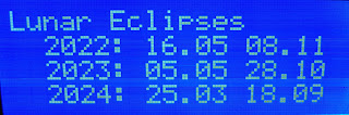
It has a new screen for predicting lunar eclipses 2-3 years into the future.

26 October, 2021

Updated Arduino Multi Face GPS Clock

The GPSClock from last month has now been updated and software version 1.10 1.1.0 is available on Github. The main upgrade is the possibility to use a rotary encoder for selecting display screen or clock face.

In addition a new screen showing Easter for the next three years, according to both the Gregorian (Western) and Julian (Eastern) calendars, has been added as number 22. The dates are shown in the Gregorian calendar:

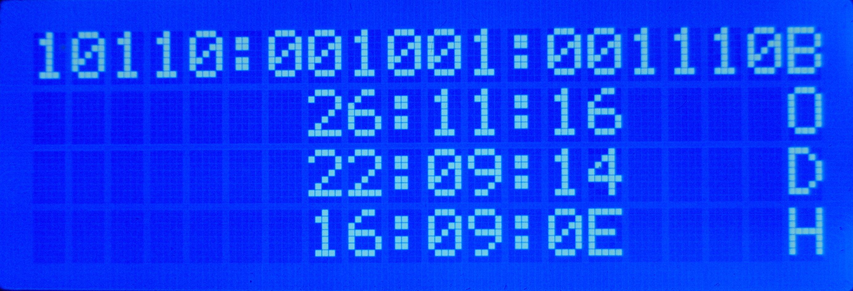
A new screen showing the clock in binary, octal, decimal, and hex format is screen 21:

29 September, 2021

Multi Face GPS Clock published

Version 1 of my Multi Face GPS Clock is here, as open source software for the Arduino Mega. It has some 22 19 different display screens showing time, location, solar and lunar positions and rise/set times. It shows UTC time as received from the GPS satellites and local time where it automatically adjust for summer time. The initial screen, no. 0, is this:

23 August, 2021

Finally figured out the moon

I’ve been working on a GPS-controlled Arduino clock for some years and had set myself the goal of showing time for moonrise and for moonset for the present day. That turned out to be much harder than I had thought.

Finally, over the last few weeks I managed to adapt lunarCycle.c to Arduino and get it to work as shown in the display here. My ambition is now eventually to publish this project on GitHub as I’ve had several requests for it.

The display here shows local time and date, moon phase on line 2, present moon elevation and moon azimuth on line 3, and the next rise time of the moon and at which position on the final line. Follow label ‘ Multi-face GPS clock’ below for more posts about this clock.

03 September, 2020

GPS corrected 10 MHz reference

My  GPS corrected 10 MHz reference now plays beautifully, as I finally was able to continue the project after a long break. All the parts were here already in February, but projects don't always develop as planned. I ended up with a modification of the F2DC Versatile Low Cost GPS Corrected Frequency Standard. It consists of an Arduino Nano, a Si5351 I2C configurable clock generator, and a GPS where the 1 PPS pulse is used to correct the frequency every 40 seconds.

27 April, 2020

GPS Clock with Binary Display

Some years ago I started making a GPS Clock with a 20 by 4 LCD, Yet another Arduino clock. It has been running since then as my shack clock. Now was the time for some additional functions, in the form of fancy variations of how to show time. I wanted a display coded in 0's and 1's, but I found that there were more than one way to do that.

The simplest one to read may be BCD (binary-coded-decimal) displays. They can be horizontally oriented like here:


10 February, 2020

Si5351 GPS corrected VFO up and running

Arduino Nano, Si5351A clock generator, I2C LCD display, and rotary encoder. The GPS signal is connected to the plug to the lower left.
I got the Si5351A Arduino controlled GPS corrected VFO designed by W3PM, Gene Marcus, up and running the other day. It gets its timing information from a QRPLabs GPS and all the functions in the original article function as they should. The main change I made was to use an LCD display running over the I2C bus, thus saving a bunch of wires from the Arduino Nano to the display.

The software worked fine except that my locator was one off in the last letter, i.e. JO59fs rather than JO59fu. I hacked the original code by adding "1" to the variable GPSlocator[5] in the calcGridSquare routine. This is not a tested fix and it may possibly have other unknown and undesirable consequences, but it works in my location.

My plan is primarily to make a 10 MHz reference oscillator out of this, as a replacement for my "Just good enough 10 MHz GPS reference" which turned out to generate too much noise in the 14 MHz band.

Now on to decide what I want to show on the 2-line display for my use and then play with Arduino code. What I definitely want is some form of indication of correction factor and thus accuracy as in the version that F2DC built.


This blog post first appeared on the LA3ZA blog.

06 November, 2016

Yet another Arduino clock

Does the world need more Arduino clocks? Maybe not.

But I needed another Arduino project as I had made a K3NG morse keyer. I love this keyer because it is unique in supporting a display where you can see what you send. But I wasn't using the morse keyer all the time, so I wanted the hardware to serve two purposes. That's the excuse for also making a clock.

Its main features are:
  • Controlled by a GPS module outputting data over a serial interface, and handled with the TinyGPS++ library
  • Shows raw GPS data such as UTC time and date, position, altitude, and number of satellites
  • Shows derived GPS data such as 6-digit locator
  • Finds local time and handles daylight saving automatically using the Timezone library
  • Finds local sunset and sunrise, either actual value, or civil, nautical, or astronomical. The library is Sunrise.
  • The clock also gives local solar height based on the Sunpos library from the K3NG rotator controller
  • Finally, the clock also provides the lunar phase based on ideas found here.
The hardware for the K3NG keyer includes a speed pot and a memory bank selector (to the right) as well as four push buttons on top for selecting memories. The pot now controls the intensity of the display, but the bank selector switch is not used. Of the four push buttons, only button 1 is used (later two are used). With it one can toggle the clock through various displays as shown below.

Local time, solar and lunar state
Line 1: Local day, date, time
Line 2: Sunrise, maximum solar elevation (actual solar angle during the day), sunset
Line 3: Civil dawn, local time at maximum solar elevation, civil dusk
Line 4: Lunar phase, arrow showing that it is rising, days since new moon

15 August, 2014

New gadget measures negative resistance

If you are like me, you appreciate electronic gadgets with dials and displays. So when I discovered this "USB detector",  I thought to myself that I really always wanted to know the voltage as well as the current consumption of my USB devices. And since it is more or less impossible to connect a multimeter, this is exactly what I need.

The device fully satisfied my curiosity. Actually one surprising result was that the charger for my Samsung Galaxy Note 8 has a negative output resistance.

30 May, 2014

Temperature compensation for an Arduino ultrasonic distance sensor

161.3 cm
27.0°  347.7 m/s
Ultrasonic distance sensors can find the range out to 2-4 meters and are popular in e.g. robotics. Here I look at how the accuracy can be improved by compensating for the variation of speed of sound with temperature. It actually varies quite a lot in air and around 0 C it is:

      c = 331.3 + 0.606 * T

where c is in m/s and T is in C. The formula is good to up to at least +/-30 C. There is also a dependence of humidity, but as it is so small it is neglected here.

The equation can be analyzed for sensitivity (a little bit of differentation, you know). The result is that a two-way range measurement creates an error of 1.8 mm/C/m. That means that with a 4 degree C error, the deviation will be 14.4 mm at a range of 2 meters. Not a lot, but more than the wavelength which is 9 mm at 40 kHz. Considering how easy it is to compensate for, then why not give it a try?