But first, I do actually have experience in blowing the finals. That happended under testing prior to leaving, and all it took was 9.5 Volts for my 9 V build and what I thought was a dummy load, but which might have been an open circuit load. One BS170 developed a short between drain and gate with the result that 9.5 Volts was passed directly into the outputs of the driver IC5, 74ACT08, so IC5 blew as well.
My three tips for avoiding such failures are:
1. Use a reduced power supply voltage for tuning
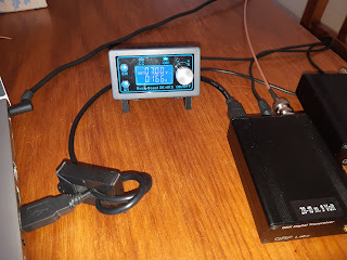
I reduce the voltage from 9 to 7 Volts during tuning. as shown in the first image. That greatly reduces the risk of getting too high voltages over the BS170s.
2. Use a current limited power supply
The image shows a limit set at 1.3 Amperes. That reduces the risk of overheating, should the current for some reason rise more than expected.
3. Use Zener diodes to protect the final transistors
This tip comes from many of the transmitters designed by KD1JV over the years and consists in connecting Zener diodes from drain to source of each pair of PA transistors. The Zener diodes will conduct if the voltage exceeds a voltage somewhat less than what the transistor is rated for, 60 Volts, and protect the BS170s.
I use 1N4756A, 47 V, 1W. I measured power output before and after fitting them and could not detect any change from 80 m to 10 m.
I have accidentally transmitted with full power into an open-circuit load after I fitted the diodes, and the QDX was just fine afterwards. I doubt that that would have been the case without the Zener diodes.
I cannot guarantee any adverse side effects of the Zener diodes, but my experience is that both the QDXes have worked flawlessly over the last few weeks, with plenty of contacts in South and North-America as well as in Europe. Those contacts have primarily been on 10 m (high-band QDX) and secondarily on 30 m (low-band QDX).
The image shows how the Zener diodes are fitted on the underside of the printed circuit board of the Rev 4 PCB of the QDX.


Thank you! Vy73 Vincent PE2V
ReplyDeleteWow! I never expected my three tips would generate this much comments and ideas on the QRPLabs discussion list on https://groups.io/g/QRPLabs/message/101779! What I have picked up from this exchange so far are:
ReplyDelete- Never run the QDX with more than the design voltage of 9 or 12 Volts. That's implicit in my three points also, especially one of the images, but it is a good idea to state it explicitly
- One should mentally think of the QDX as having a nominal 4 Watts of output, with 5 Watts as a bonus. Fewer experimentalists (like me) would then be tempted to try to squeeze the final Watt out of it, and more PA transistors would have survived. The number of QSOs would probably not have changed much.
I have learned a great deal about many aspects of the hobby prior to the finals burning up.
Delete1) When Hans publishes a specification on a kit; that is the spec., don't deviate. (polarity is critical as well...)
2) I am a kit building novice, but I owe QRPLabs for allowing my kit experience to be a great one that worked when I finished it.
3) While making hundreds of contacts with this transceiver I never expected it to be this good, even after the abuse I put it through.
4) All this adds up to mean that, I am a much better Amateur than I was before I started this hobby. Thank you Hans!!
Sverre I appreciate the intellectual hind sight on how i should now go forward and fix this tiny awesome project!
James KI5OEB
Nice to hear - isn't it all about learning and making progress?
DeleteHi Sverre, I managed to burn up two times a BS170 of my QDX High Bands. Each time I replaced the BS170s and the 74ACT08. Now I never use more than 10-11 V. Thats enough for 3-4 Watts. In addition I installed the Zener diodes. Also I did this for my Two TruSDX trx. Its a very good idea to protect the P.A. with Zener Diodes. Thank you for the inspiration :)
DeleteCan i use a different diode then a zener to accomplish this. At the moment i have no zeners.
ReplyDeleteThere is no point in anything but a Zener diode with a Zener voltage around the value I have used - 47 V. The point is to have a Zener voltage as high as possible but below the breakdown voltage of 60 V for the BS170, so that the diode limits the voltage to a value below the breakdown voltage. An ordinary diode will have no effect.
DeleteAh, I see reasoning now. I thank you for the response. I am almost finished putting my ver5 qdx together. I will order some zeners.
DeleteSverre,
ReplyDeleteI’m fairly new to the electronics world. I understand what a diode does but can you explain how the Zener diode works in this circumstances. I would like to protect my 12v QMX however I can. This sounds like a great dea but I guess I don’t quite understand the theory behind it. Why would you need a breakdown voltage so high?
Thank you,
Robert
Here's a good description on YouTube: https://youtu.be/7hUmkE84kfA?si=xF058LbiV0pVzDHT
DeleteWhat are the added capacitors on the underside of the board for?
ReplyDeleteIt is a decoupling of the center tap of the output transformer, where it is connected to L14. Something like what's mentioned here: https://groups.io/g/QRPLabs/message/102347 and https://groups.io/g/QRPLabs/message/104108.
Delete