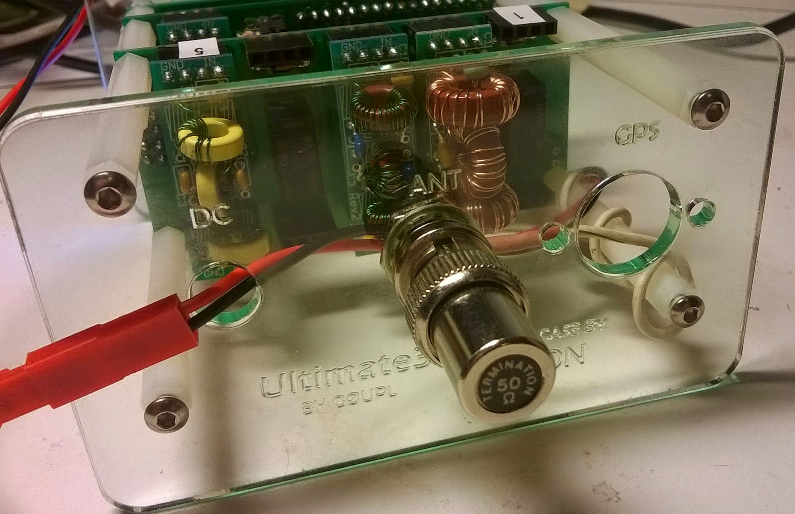
For the first time ever I have been spotted on all the five bands that my Ultimate3 QRSS/WSPR kit (G0UPL design) is transmitting on. This is after 2-3 days of transmitting.
Right now I am using the beacon for discovering if the bands should open up on 24 and 28 MHz. The other three bands, and especially the 14 MHz band, serve as references to tell me that the transmitter is working. My antenna is not so optimal so I would be surprised if I am spotted far outside Europe. It is an end-fed 5 m long half wave vertical dipole which isn't too bad for 28 and 25 MHz, and probably not very good at all on 21, 18, and 14 MHz.
07 August, 2014
02 August, 2014
Nice radio-related stamp
A few weeks ago I had one of my rare visits to the post office. As I was waiting, I saw a display of a new series of stamps and I just had to buy the one shown here. What caught my attention was not really the artist, but rather the Kurér portable radio.
The stamp was of course not about the radio but was issued in commemoration of the 100 year anniversary of the birth of Alf Prøysen. The English Wikipedia page has this to say about him:
20 June, 2014
Disappointment with Spice and the QRP-er's favorite, the LM386
The trusty old LM386 audio amplifier from the 70's is still used a lot in low power and portable equipment. Recently some ultra high gain circuits have been recommended that I wanted to simulate with Spice. I started with the datasheet examples for checking the quality of the model. The result was surprising.
In the data sheet one can find a minimum parts circuit, a high gain circuit, and a bass boost circuit:
![]() | ![]() | ![]() |
Gain = 20 (26 dB), minimum parts
| Gain = 200 (46 dB) |
Bass Boost
|
30 May, 2014
Temperature compensation for an Arduino ultrasonic distance sensor
![]() |
161.3 cm
27.0° 347.7 m/s
|
c = 331.3 + 0.606 * T
where c is in m/s and T is in C. The formula is good to up to at least +/-30 C. There is also a dependence of humidity, but as it is so small it is neglected here.
The equation can be analyzed for sensitivity (a little bit of differentation, you know). The result is that a two-way range measurement creates an error of 1.8 mm/C/m. That means that with a 4 degree C error, the deviation will be 14.4 mm at a range of 2 meters. Not a lot, but more than the wavelength which is 9 mm at 40 kHz. Considering how easy it is to compensate for, then why not give it a try?
19 May, 2014
Nice, watery CW signals from Alaska
![]() |
| Great circle path between Anchorage and Oslo |
The characteristic sound of a CW signal that has passed over a moderate geomagnetic disturbance (Kp = 2) isn't too hard to recognize with a little practice. There is also some static on this short recording as we had a local thunderstorm coming in with the first summer days here.
The great circle distance between the two cities (actually their two airports) is 6446 km as illustrated by GPSVisualizer. Anchorage and Oslo are about at the same latitude, 61° N and 60° N, respectively. As they are at longitudes 149° W and 10° E, there is a difference of 159 ° - almost 180 ° - and this means that the signal almost passes directly over the North Pole, although a bit hard to see on the projection used in the map.
03 May, 2014
Practical Wireless with the LM386 unleashed
Then he goes on to talk about various ways to improve the circuit such as for hiss reduction and even higher gain. In that connection he also mentions my article "Unleashing the LM386" from SPRAT in the Autumn of 2003. That circuit was an enhanced version of the high-gain circuit of Kazuhiro Sunamura JF1OZL. Basically it increases the gain to up to more than 70 dB, enough for it to drive a loudspeaker. My circuit also adds bandpass filtering. All this is achieved by adding only 5 passive components to the basic amplifier. The circuit was recently revisited in SPRAT by Johnny Appel SM7UCZ. He added a 40 dB Darlington pair preamplifier for even further gain.
The bandpass filtering (not low pass as the article says) is due to the series resonance of 100 uF and 1 mH which happens at about 500 Hz making it a nice CW filter.
24 April, 2014
Pulled out my dummy load tonight
![]() |
| Press image for a better view of the dummy load |
It measures just 9-10 mm across and is the size of a BNC connector. It is simply one of the many Ethernet terminations that I have lying around. Its built-in 50 ohm resistor is rated at something like 0.25 W. Considering that the kit outputs something like 200 mW that should mean that there is enough margin and no forced air cooling or liquid cooling is required.
06 April, 2014
Bletchley Park, Enigma, and GB3RS
![]() |
| Enigma (Photo: R. Holm) |
In order to perform this work a large effort in the development of early computers took place here. They include the mechanical Bombe for breaking the Enigma, and the valve-based Colossus for breaking the Lorenz.
The Bombe was reconstructed through a 13 year effort that resulted in an Engineering Heritage Award in 2009.
Subscribe to:
Posts (Atom)