 |
| Cable with large distance between the conductors (Schnerzinger) |
The first example had a large distance between the conductors and was placed on its own stand to get distance from the floor. It was designed to minimize capacitance between conductors. Another design criterion was to minimize the impact of vibrations created by the speakers themselves.
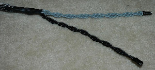 |
| Twisted multi-conductor cable |
There is no shortage of science-based claims for how cables affect sound. There are so many of them that this blog post, where my ambition is to say something about all of them, gets to be a little longer than I would have liked it to be. If you are impatient, you may go to the end and just see the conclusion. For the curious, I will consider the claims one by one.
After resistance, it is inductance and capacitance that matter. But is a small inductance or a small capacitance preferable? Ideally, both should be zero. A cable can be made with a small value for one by getting a large value for the other. But it is not possible to produce a cable with both low inductance and low capacitance. And whether you have much of one or the other, they will both influence the treble. A hand-waving way of saying it, is that inductance blocks high frequencies while the capacitance short-circuits them. And even in a regular short speaker cable, this means that the bass will arrive a little later than the treble (dispersion).
But in a normal short speaker cable, the difference in time delay does not correspond to much more than if the tweeter element in the speaker was moved a maximum of one mm back, so the consequence is minimal. In addition, the attenuation of the treble is so small that it can be neglected in most cases. If you still want to minimize the loss for high frequencies, it pays to design for a low inductance rather than low capacitance. In other words, it is an advantage that the conductors are close together as they are in most cables, and not far apart as in the cable in the top picture. I’ll come back to why at the end of the article.
Some cable designers emphasize minimizing the reflection of the signal from the ends of the cable. That means adapting the load to the cable's characteristic impedance. This is well known from cable TV where the impedance of the transmission line is 50 or 75 ohms. There are several objections to impedance matching for speaker cables. First, it is not possible to make cables with impedance as low as 4 or 8 ohms as is typical for speakers. But even more important is that a TV cable is long in relation to the wavelength of the signal. That is what makes the transmission line model applicable. This is not the case for audio cables where the highest treble has a wavelength of at least 10 km and the bass even longer. Therefore, speaker cables cannot be understood as transmission lines and all talk of impedance matching is meaningless.
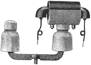 |
| Pupin coil on insulator on top of a telephone pole (American Electrician 1903) |
Others emphasize that their cables avoid resonance. This may sound convincing, as a system that has inductance and capacitance always has a resonant frequency. Even here there is a mixture of two models. The low frequency model of a cable, the one that applies to audio, consists of a discrete inductance and a discrete capacitance. Using typical values, one will find a resonance frequency of a MHz or two, which is far higher than what is audible. This fact alone should indicate that the effect is insignificant. Even more important is that at these frequencies, there is another cable model that applies, namely the transmission line model mentioned above. It has distributed inductances and capacitances and that gives no resonance. Therefore, the whole resonance problem is yet another imagined problem due to incorrect application of models.
Closely related to resistance is the skin effect. This means that the higher the frequency, the more current is displaced to the outer part of the conductor. Even at 50 Hz, as in the electricity supply, the current does not penetrate much more than one cm into a copper cable. At 20 kHz, the skin depth is about 0.5 mm. This means that for thick cables (2.5 mm2 and more or AWG 10 and less) the effective resistance increases slightly with frequency. The proximity effect, which is how currents in the two conductors influence each other, also contributes in the same direction.
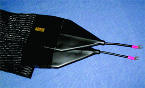 |
| Flat cable which is 12.5 cm wide (Magnan Audio Cables) |
A third way to deal with the skin effect is to make a hollow coaxial cable, as used for cable TV. The expensive Pear Anjou cable that annoyed James Randi, was built this way (see part 1). However, compared to the increase in impedance due to the inductance of the cable, the contribution from the skin and proximity effects is not very large. Still, it does not hurt if a cable minimizes these effects, but it may be questionable whether it is worth the money. The skin and proximity effects are real effects that can be measured. They illustrate the fact that even if something can be measured and analyzed, it does not necessarily mean that it is important. Designs like that of the twisted multi-conductor cable shown above are despite this reservation to be recommended.
How can it be that some exotic cables are made with a large distance between the conductors to get low capacitance, when I have just said that it pays to have small inductance? Often it is because they have focused on a memory effect found in capacitors and which is due to dielectric absorption. Even when a capacitor is what appears to be fully discharged, it may still remember some of the charge. I have illustrated this in a YouTube video. This is a real effect, especially in capacitors with high capacitance, much larger than in a cable. It has to do with the quality of the material between the conductors. Materials such as Teflon minimize it, but even better is air such as in the cable that floats on stands above the floor in the picture above. A cable supplier can make it a point that their Teflon insulation cures such effects and explain how cables can be 'non-linear' and smear the sound and give a bad stereo image. Is it real? Not really, as the memory effect is linear since it can be modeled with a network of capacitors and resistors, none of which can distort a signal non-linearly. This has been illustrated by analog guru Bob Pease.
Then there are those who emphasize the importance of proper materials in the conductors. As mentioned earlier, good conductivity is important. With its good conductivity, acceptable price, and good mechanical properties, it is no wonder that copper is so popular. It is barely beaten by silver which has 5% lower resistance than copper. Gold does not come out so well as it has almost 50% more resistance, but it is well suitable for electrical contacts as it does not oxidize. You can get expensive speaker cables made from silver. But the question is whether it is not better to increase the copper cross sectional area by 5% rather than use the much more expensive and mechanically more fragile silver.
There are also many who emphasize the purity of the material. Here it is appropriate to say something about how a signal is conducted along a cable. A common analogy is a water pipe. In a cable, it is the electrons that are said to flow like water in the copper. But this analogy starts to falter when you look at the transport velocity of electrons in a material like copper. It increases with frequency but never becomes more than a few tens of m/s. Let's say that a power plant located 500 km away starts up and the current is transported by electrons traveling at 10 m/s. Then it will take almost 14 hours before I notice that the power has been turned on! Here, the analogy with the water pipe has obviously broken down.
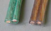 |
| Nobody likes corroded cables |
The same applies to those who argue that there will be distortion if the cable consists of several strands. For this reason, there exist rigid and unwieldy speaker cables made from solid copper. The idea is that there will be a rectification effect in the transition between the various strands, i.e. between copper and oxidized copper, much like in a crystal in an old-fashioned crystal radio. But this is also energy which is lost as heat. Moreover, such a distortion should be possible to measure, but I have never seen such measurements. The argument that the cable needs a break-in period of several hours or more, as well as the idea that it is important which direction a cable is connected also fall on its own unreasonableness. Remember, however, that it is still important that both speakers are polarized in the same way, so it does matter which of the two cable ends is connected to which of the speaker terminals. But this is a pure acoustic effect to ensure that both speaker diaphragms move in and out in phase and it has nothing to do with the properties of a cable.
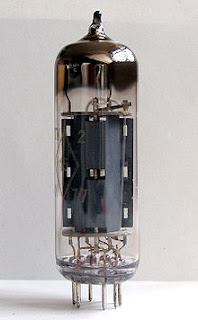
When it comes to tube amplifiers, some may have noticed that knocking on a tube sometimes can be heard in the speaker. This is a mechanical or triboelectric effect that also can happen in poor quality microphone cables. The danger is that the sound pressure from the speakers themselves can cause the cables to vibrate and create distortion. Some people get hung up on this in the design of speaker cables and argue for choosing geometry and insulation materials based on it. Since it is possible to design microphone cables which are robust against such effects with their very low signal levels, it goes without saying that this cannot be an important effect in a speaker cable where signals are so much stronger.
There is also an effect which in a way is the opposite of that in the previous paragraph. Due to the large currents in a speaker cable, there may be forces between the conductors that can make them attract and repel each other. If this leads to movement, it can give rise to a new signal which can disturb and distort the actual signal. This is used as an argument for putting the conductors far apart. But the cure must rather be to make a mechanically stable construction. Besides, this is also an effect which should be measurable. I have even tried to measure it myself without success. Therefore I doubt if there is anything here to worry about.
What should we conclude, is there magic in speaker cables? We have looked at the effect of a large and a small distance between the conductors, on reflection and resonance, on skin and memory effects, on the purity of the conductor, whether break-in and polarizing the cable is important, on vibration effects and finally on potential interference from external signals. One factor that has deliberately not been discussed is the aesthetic value. It should not be underestimated that hi-fi sells both on acoustic performance and on pleasing design.
But from a purely performance point of view, I end up with the finding that low-resistance, low-inductance cables are well supported. The most common and cheapest type is with conductors next to each other, but they may be twisted together as well. This means that the cables can be quite affordable as long as they have a cross section of at least 2.5 mm2 (AWG 10). In professional audio, 2 x 4 or 2 x 6 mm2 are often used (AWG 6-3), unless they use active speakers where there is hardly any cable at all. Twisted multi-conductor cables are often not very expensive and may possibly have an edge at high frequencies. In any case, the longer the cable, the thicker it should be. Due to the possibility of radio frequency interference, exotic cables with a large distance between the conductors are something I want to warn against. The same goes for high-inductance cables with discrete inductors embedded in them, all other exotically designed cables have no negative effects, other than possibly on your wallet. And since no cable is ideal, the recommendation is to make it as short as possible, but still the same length for each speaker.
Sources:
- Greiner, Richard A. "Amplifier-Loudspeaker Interfacing." Journal of the Audio Engineering Society 28.5 (1980): 310-315.
- Robert A. Pease, "Understand capacitor soakage to optimize analog systems." EDN, Oct. 13, 1982.
- Davis, Fred E. "Effects of cable, loudspeaker, and amplifier interactions." Journal of the Audio Engineering Society 39.6 (1991): 461-468.
- Edwards, John, and Tapan K. Saha. "Diffusion of current into conductors." Australasian Universities Power Engineering Conference. Vol 1. CRESTA, 2001.
- Black, Richard. "Audio Cable Distortion is Not a Myth !." Audio Engineering Society Convention 120. Audio Engineering Society, 2006.
- Newell, Philip, and Keith Holland. Loudspeakers: for music recording and reproduction. CRC Press, 2006.
(First published in Norwegian in: Magiske høyttalerkabler - del 2)
The post "Magical speaker cables - part 2" first appeared on the LA3ZA Radio & Electronics Blog.
Excellent articles Sverre. Really enjoyed to read this. I just keep my simple wire to my speakers. The only thing I always add is ferrite just behind the amp and just behind the speakers. Just to prevent the wires to pick up RF from my station. 73, Bas
ReplyDelete